# Devices
This page manages the devices connected to the platform and provides interface with this system.
# Side panel
The configured devices are listed on the left, with their name and a switch to control their power-on status.
The icon and the label take on color
- blue, to identify the device currently selected and displayed in the view;
- otherwise
- grey, to identify a device that is off (and not currently selected);
- green, to identify a device that is on (and not currently selected);
- red, to identify a device that is switched on, but which is not responding (it can be timeout or network connection interruption); in this regard, check the power on status of the device, and that the connection in the network is active with the correct IP address.
Whenever ther are two or more devices, a button to reorder them is displayed, labeled "Edit Order": Clicking it opens a popup in which you can drag the elements into the desired order and then save, or possibly cancel the changes.
# Add a device
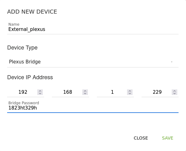
Adding a new device is done by clicking on the button labeled "ADD DEVICE", which opens a modal with the following elements
- Name, the descriptive label to be assigned to the device, which must comply with the Plexus nomenclature criteria;
- Device type, the type of device connected;
- IP address [for any type except Profinet], the IPv4 address configured for the device on the network;
- Password [only for Plexus Bridge], read below for further informations;
- Port and Registers [only for Modbus], read below for further informations.
# Types of devices
To date, PlexusLAB offers the possibility to add one or more devices among the following types
| Name | LTS | Information |
|---|---|---|
| PlexusPOD 0-10V | POD which allows operation with elements at 0-10V | |
| PlexusPOD 4-20mA | POD which allows operation with elements at 4-20mA | |
| PlexusPOD C1 | Future version of the POD in production from Q3 2021, which allows the possibilities to switch individually the analog / digital channels operate at 0-10V or 4-20mA | |
| Plexus 1 | Old version of the POD dated 2016, being discontinued | |
| Plexus Bridge | Virtual, to connect another PlexusLAB Web Server and interface with the sections of the latter, which acts as a bridge; in the “Bridge Password” field it is necessary to enter the password to authenticate the connection to the target PlexusLAB. Refer to this paragraph for more informations | |
| Modbus | A communication protocol already on the market, used by several devices and automation systems, like PLC. The addition of a device of this type involves the insertion of additional values that indicate the ranges of registers with which to interface in reading / writing to the system that uses Modbus, in the four fields “Start read Register”, “End read Register”, "Start write Register”, “End write register” | |
| Profinet | An industrial automation system already on the market. PlexusLAB has an interface to read and write multiple values from an existing Profinet I/O device |
# Command the status of the device
Each device has a switch next to the name, which controls its status.
When a device is turned off (gray switch) its status is Not active in the view and all values will be shown at 0.
When a device is turned on (green switch) the following conditions may occur in the view:
- State in Green with indication of the milliseconds measured as response time. In this case the device is up and running, the view shows information on the channels in real time;
- State in Timeout!, status indicating that the device is not responding, so all values will be 0 in the view. Investigate one of the possible causes of the problem, which are usually:
- misconfigured IP address;
- lost connection;
- worst case scenario, device failure
# Re-ordering the devices
It is done by clicking on the "Edit Order" button at the bottom of the device list; note that the button is shown only when there are at least 2 devices configured.
When clicked, a modal window is displayed that allows you to drag the rows and, if necessary, save the new order in order to see the list with the desired structure.
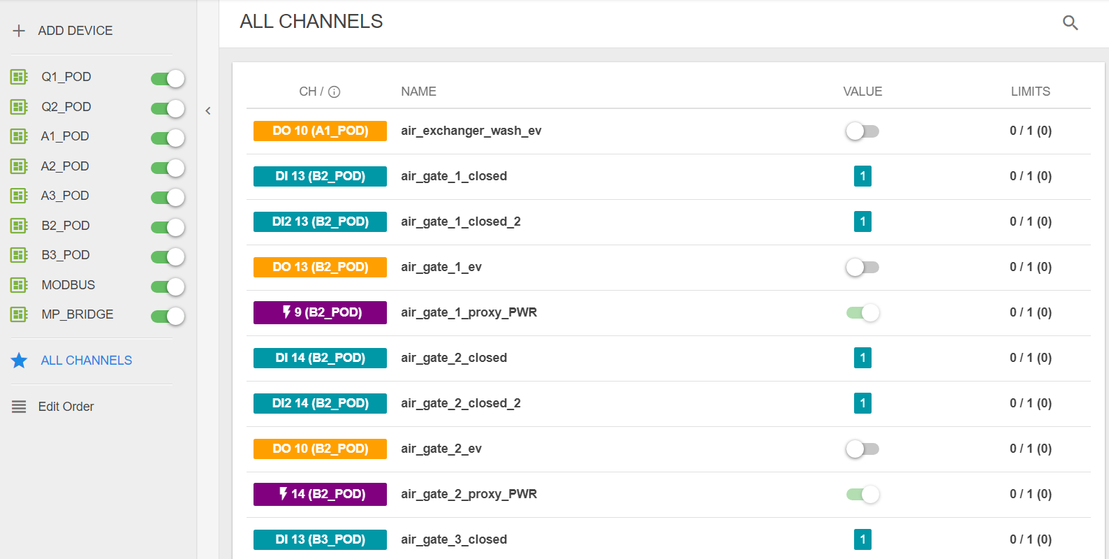
# All channels sorted alphabetically
The "ALL CHANNELS" button allows to access to the list of all channels of all devices, sorted by their name. It is possible to select this button only if these 2 conditions are verified:
- there's a minimum of 2 devices available;
- the user is logged as a "Super Admin"
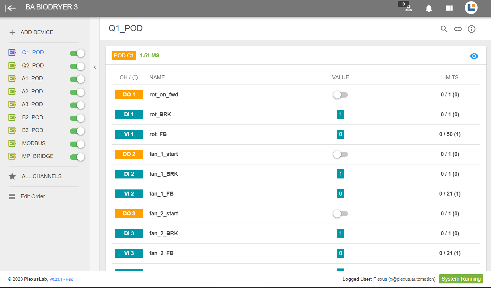
# View
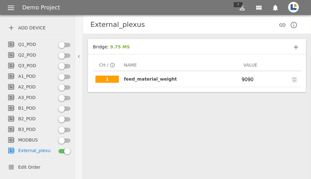
The View is the portion of the screen dedicated to the detail of the currently selected device (blue icon and label in the list).
The name of the device is shown at the top, a badge which indicates its type, the IP address configured and clickable for it (to access the configuration screen inside the device itself) and finally an info button that allows you to modify the configuration that are previously set when adding the device.
# Edit a device
You can edit the device IP Address and Device Name by clicking on the info button at the top right.
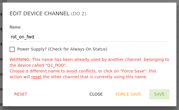
It is also possible modify every channel of a devce clicking the coloured labels in the first column of the table:
- change a channel name. Plexus will tell you a pin is named in the same way of another one. In this case, a change of device name is mandatory.
- Forcing name of a channel. This can be pretty useful in all those cases when the same named given to a random channel (X) is already used to by (Y). In order to avoid mistakes, this option will call (X) with the new name and a standard label will be assigned to (Y).
Analog values conversion. For every Analog channel , both input and output, it's possible to define an interval (minimum, maximum) to re-scale electrical values (they are usually 0-10V or 4-20mA).
For example, a thermocouple output is between 4-20mA, related to 0 and 100 C. The conversion associates 4mA to 0C (minimum) and 20mA to 100C (maximum).
Other parameters can be set, "Dec Value" is the number of decimals displayed and "Offset Value" is used to centre the converted response in a non-zero point.Power Supply, every Digital output pin has this feature. Flagging this option will set the channel to 24V and you won't be able to modify it during program execution.
# I/O channels
A device is usually provided with I/O ports. Our Plexus Pod has 14 ports which are also divided into Analog or Digital channels.
# Channel types
| Icon | Functionality |
|---|---|
 | Digital output, can be either 0 or 1 (0V or 24V) |
 | Power supply, a digital output whose value is set to 24V during program execution and can't be modified |
 | Digital input, reads boolean values (0 or 1) |
 | Analog output, is able to provide a voltage between 0 and 10V or a current between 4 and 20 mA |
 | Analog input, read voltage or current standard values |
# Channel disabled
A channel of a Device can be disabled by the Functions. In this case, it will not be possible to change its value and its name will be crossed out.
# Channel reset
WARNING
The "Reset" option allows you to bring back a channel to its default state. This means deleting its name and value. Errors in program execution may occur if every time the resetted channel is used in the code is not properly modified.
# Remove a device
You can delete a device by clicking on the info button at the top right and click on "Delete".
# Plexus Bridge
Plexus Bridge allows you to interconnect two or more PlexusLAB(s) together; this may be useful when there is more than one single network in the enviroment and you want to control all your PlexusLAB(s) from a Master machine without moving between them.
PlexusLAB must be installed on each machine you need to link, of course. For example, you can have:
- an Ubuntu OS machine (A) on a private subnet, connected directly to a PlexusPOD
- a second Ubuntu OS machine (B) exposed to the public network, with no PlexusPOD connected directly to it
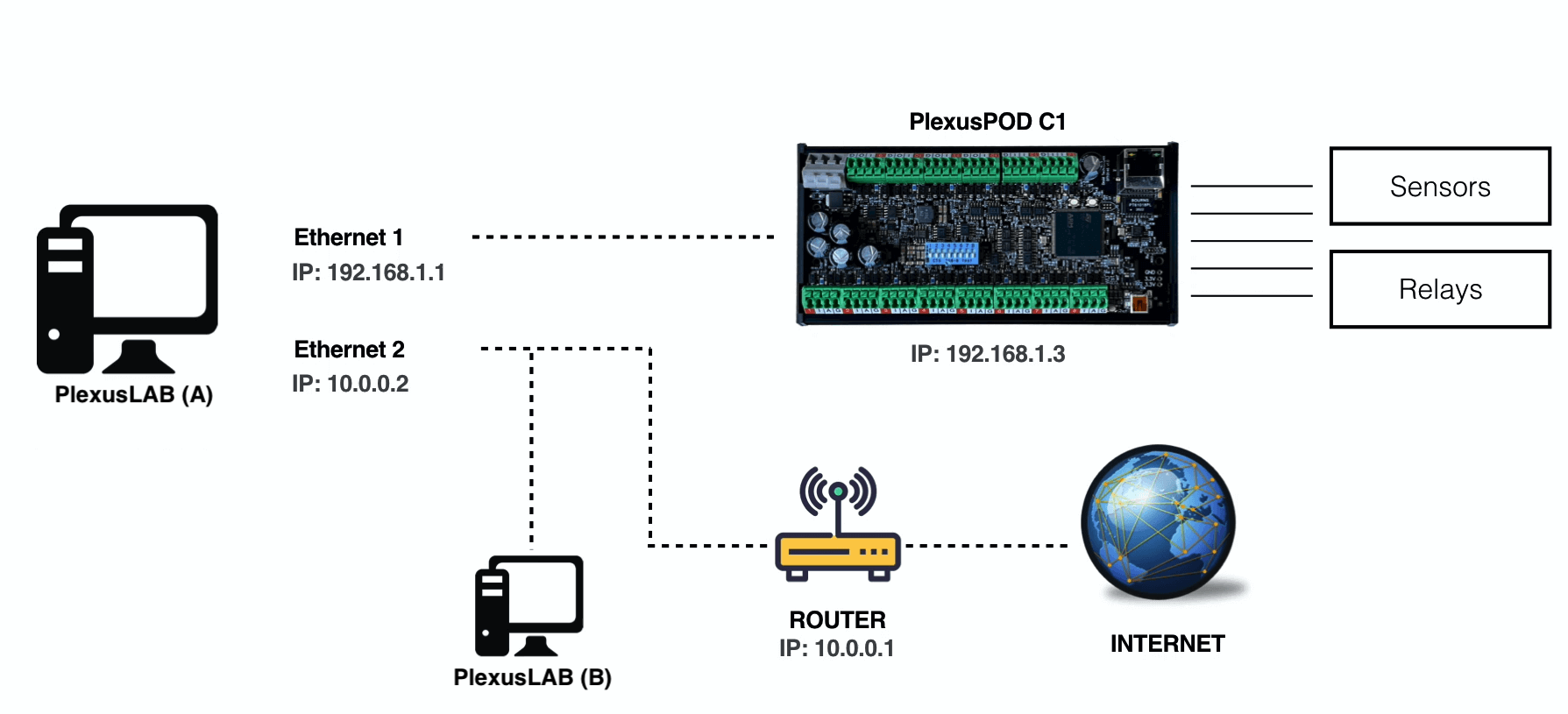
You're able to retrieve the variable/data from (A) if you register and connect (B) to it.
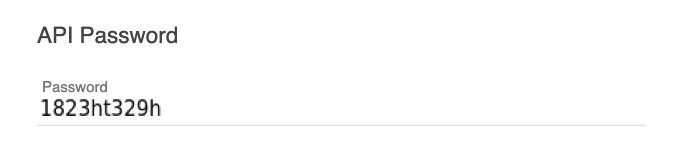
To start, make sure both PlexusLAB(s) have the API/Bridge Mode turned on in the System page.

TIP
Enabling API / Bridge means activating REST APIs for the system. This allows any third party to read and write any variable in the section: this can be useful to let anybody create custom dashboards outside PlexusLAB pages. See the appendix for an explanation on how to call the REST APIs.
# Bridge configuration steps
The following steps refer to (A) and (B) from the previous example:
| Step | Operazions inside Plexus (A) | Operazions inside Plexus (B) |
|---|---|---|
| 1 | Copy the password from System > Bridge Mode configuration | - |
| 2 | - | Add a new device of type "Plexus Bridge" |
| 3 | - | Paste the password taken from (A) in step 1; use (A) IP in the IP field, of course |
| 4 | Add (or use an existing) variable inside the sections, to be read from (B) | - |
| 5 | - | Add a new channel to the device created at step 2, using the same exact channel name of the variable at the step 4 |
| 6 | - | The channel created at step 5 will be populated by reading (A) |

# Modbus
PlexusLAB allows users to communicate via Modbus TCP/IP protocol. In order to do so, the platform can either interface as a Client(Master) or as a Server(Slave) device.
# Modbus Server
To enable the Modbus Server functionalities, navigate through System - Modbus Server Mode, press the info button and fill in these fields:
- Modbus IP address, it is the IP address you want to connect to, the one assigned to the machine hosting PlexuLAB.
- Modbus Port, the standard value for this field is 502.
Then, yurn on the Modbus Server Mode by clicking on the "Toggle status" button.
TIP
The device added in this way can be the Server created by PlexusLAB. In this case just fill-in with the same IP address of the machine where Plexus is installed on.
WARNING
IThe Modbus Server device of PlexusLAB is not compatible with the Modbus Protocol's function code 23. In the case that connecting together both the Client and Server devices created by PlexusLAB is needed, use a device whose version is FC16&FC3.
# Modbus Client
PlexusLAB is capable of communicating as a Modbus Client on a Modbus network, this means connecting with multiple Server devices through their IP addresses. In order to add a device inside the list of those which are available to the Client for communication, navigate through Device - Add device, assign a name and select "Modbus" type. Then fill in these fields:
- Device IP address, address of the device you want to connect to.
- Modbus Port, standard value it's 502 but can change according to the device.
- Version, select the version of the Server you want to communicate with. The version depends on the instructions that are compatible with it.
- Start read register, starting number of the block of reading registers.
- End read register, ending number of the block of reading registers.
- Start write register, starting number of the block of writing registers.
- End write register, ending number of the block of writing registers.
- Shift registers, put a check in case the Server device has a "zero-based" numeration of its registers. Leave it blank otherwise.
WARNING
Reading and Writing registers can have consecutive or not address numbers. This depends on the Modbus Device's version.
| Version | Description | Compatibility |
|---|---|---|
| FC16 & FC3(retro-comp.) | Use it with Modbus devices that are compatible with function codes FC16 (multiple registers writing) and FC3(multiple registers reading). | Compatible with devices whose writing registers range must be inside the one of the reading registers. Not supported by PHP 8.2 |
| FC16 & FC3 | Use it with Modbus devices that are compatible with function codes FC16 and FC3. | Compatible with devices whose writing registers range can be different from the one of the reading registers. Supported by PHP 8.2 |
| FC23 & FC3 | Use it with Modbus devices that are compatible with function codes FC23 (writing and reading of multiple registers) and FC3. | Compatible with devices whose writing registers range can be different from the one of the reading registers. Supported by PHP 8.2 |
# Profinet
BETA
Note: This feature is currently in Beta: stability issues might occur.
PlexusLAB allows a user to perform data exchange with a PLC Controller on a Profinet network (tested with Siemens PLC Controller) acting as a PLC I/O Device.
Contact us for more informations, we might provide you with the GSDML descriptor to be installed in the Profinet system, in order for the Controller to estabilish a connection with the PlexusLAB machine.
By installing a Profinet device, PlexusLAB will provide the Profinet network with the following set of I/Os:
- 16 digital outputs (bool)
- 16 analog outputs (uint16, ranging from 0 to 65535)
- 16 digital inputs (bool)
- 16 analog inputs (uint16, ranging from 0 to 65535)
# Profinet configuration steps
- Set the desired network interface name of your machine (i.e.: enp0s31f6) exposed to the Profinet network in the Settings Page
- Turn on Profinet I/O Mode in the Settings Page
- Create a Profinet device in the Device Page